|
|
|
| Extruders | |
| Testing facilities | |
| Location | |
|
WELDING ENGINEERS LTD. |
|
Rue Saint Léger 4 - CH-1205 GENEVA SWITZERLAND |
|
|
|
HOW DOES WELDING ENGINEERS DRY SYNTHETIC RUBBER? 1. INTRODUCTION OF THE MAIN EQUIPMENT: EXTRUDERS, TURBULATOR AND DRYER 2. PROCESS DESCRIPTION OF THE SDU, VCU, TURBULATOR AND TCU 3. ADVANTAGES OF THE WELDING ENGINEER'S DESIGN 1.
INTRODUCTION OF THE MAIN EQUIPMENT: EXTRUDERS, TURBULATOR AND DRYER
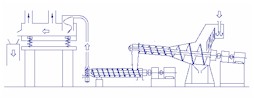
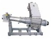
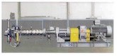
The principle of operation of our dewatering extruders (SDU) and drying extruders (VCU) has not changed since the early days. The design has however been constantly developed to meet the industry's new challenges for higher performance, reduced emissions, lower maintenance and ever increasing online time. In the following pages we present a general description of Welding Engineers' latest system for drying synthetic rubber. The word "latest" implies, of course, that we designed other system prior to this one. In point of fact, our first system went into operation as far back as in 1946. Welding Engineers' rubber drying system accepts slurry containing as little as 5 percent solids, thus direct from the slurry tank, using no shaker screen for initial water separation, and delivers rubber dried to specification in pellet or crumb form. The system comprises the following main equipments: A. The Slurry Dewatering Unit (SDU) The mechanical compression separates the water from the rubber which is discharged in the form of large chunks to feed the VCU. B. Volatiles Control Unit (VCU) Rubber temperature is increased by shear at controlled conditions. C. TURBULATOR Fixed at the end of the VCU permits to adjust the pressure and temperature in the VCU. It consists of a variable die (adjustable during operation), a pelletizer and an airveying system. Moisture is flashed, rubber is cut in particles of optimum size and airveyed to the TCU. D. Temperature Control Unit (TCU) The particles of rubber are fluidised and conveyed on a cushion of hot, dry air which removes the residual moisture. It can also include a cooling zone to reduce the rubber temperature to optimum baling conditions.
2.
PROCESS DESCRIPTION OF THE SDU, VCU, TURBULATOR AND TCU
Slurry Dewatering Unit (SDU) The aqueous slurry coming from the slurry tank, is admitted through a pipe into a feed tank from which it flows uniformly over a static wedge bar screen . The crumbs, thus separated from the free water, fall into the feed section of the dewatering screw. The
screw, mounted at an angle, is designed to accept the crumb, forward it
into the compression section of the screw and discharge it through a
variable die. Cutting is accomplished by knives turning with the screw.
The variable die allows to optimise the pressure conditions and thus
the dewatering during operation. The water expressed from the rubber flows backwards inside the barrel towards the feed zone. The water is removed through drain openings located in the conical and feed barrels. The extruder (feed sections and barrels) is entirely closed. No water on the floor and no steam inside the plant building. Two flanges, permit evacuation of vapour. Water drains are directly connected to customer recycle water system. There are no slots or other drain openings that would plug, interrupting the process or causing large variations in the degree of dewatering. Barrels are jacketed for preheating. The screw can be supported by bearings at both ends, with no contact between screw and barrel. This
is a specially designed extruder for controlling the residual volatiles in
the product. The feed section with large volume assures good
acceptance of the product from the SDU. A drain permits to evacuate
any residual water expressed during the initial compression stage. The
cylindrical section generates the pressure and temperature required to
bring the product to the die at optimum conditions. Barrels are
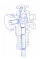
jacketed for The die is incorporated in a special device, the TURBULATOR, patented by Welding Engineers. The die holes are drilled through two concentric sleeves. The moist rubber driven under pressure through the die holes immediately
The Turbulator can be equipped with a quick opening device. Temperature Control Unit This is a vibrating conveyor with a perforated deck. Air is blown from the plenums beneath the deck and through the product. The system comprises blowers and steam batteries with control for air flow at desired temperature and velocity for the particular operation. The particles of rubber from the Turbulator are thus conveyed in a fluidised stream, each particles surrounded by air, offering maximum efficiency by initially heating and then if desired, gradually reducing the product temperature to the required level for baling or bagging. An exhaust hood to remove all the process vapours is mounted over the conveyor. 3.
ADVANTAGES OF THE WELDING ENGINEER'S DESIGN
|
||||||||||||||||||